Tuesday, February 08, 2005

The Sound

My T12 is into 10 hours of burnin and the sound is much better. The high and low extension is very more extreme, the base are tight with good control and the sound stage is very realistic and pin point accurate. It is also a very fast amp, listerning to large orchestreal piece does not show any trace of looseness. Overall, I am extremely happy with its performance!

Saturday, February 05, 2005

Testing

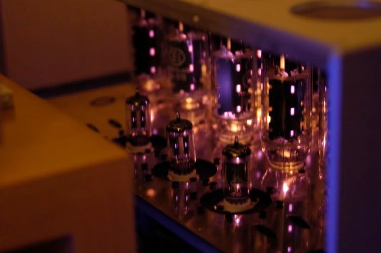
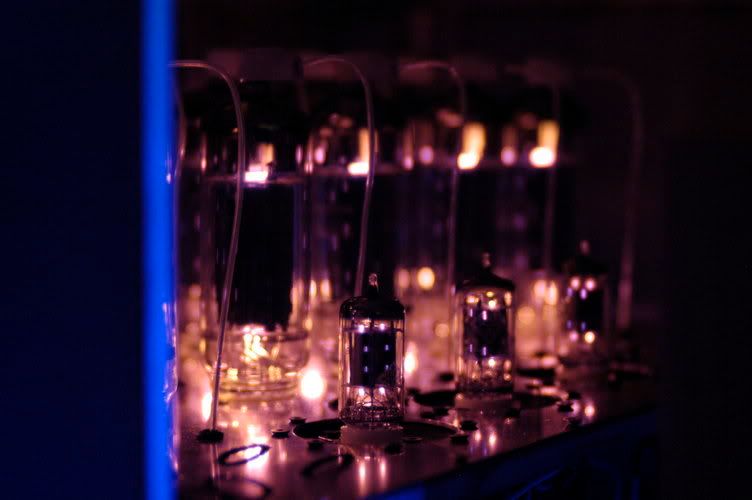
All voltages are very close to what specified on the book. But each time I switched on the amp, the bias takes about 15 minutes to settle to the 0 value. Initiall, I it takes awhile to burn that it to make it more stable. But after asking in Transcendent forum, Bruce told me that there is a tube that is marginal. I can sort of pick the tube as it glows much more than the others. After changing this tube, everything is back to normal. Settles pretty much at the start.

Initial impression of the sound is very very good! I have heard this amp in my friend's home, but when I hear my own creation in myown house. This is really touching. The extension to both ends are very good at the start already The control of the base is very good and the amp is extremely fast. There are a lot more datails I can hear now that just wasn't audible before.

Now I am burning it in with the STS Burn-in CD with the speaker terminal connected to a 100W 10R resistor. Hopefully, this will speed up the burn in process without causing complaints from my neighbours.

The amp is running quite hot though, I measured the top cover of my amp and it is recorded 60deg!


I would like to thanks Bruce for creating such a wonderful amp and made this available to all of us!

Circuit modification

I have made some modifications to the circuit shown in Audio Reality based on my friend's comment.

1. C5 & C6 is now combined to 22uF 630V Solen
2. All voltage doubler were changed to full bridge
3. All electrolytic ripple rejection caps on the 550V and negative bias were changed to solen MKP
4. All Caps on the +/- 170V were parallel with 0.1uF MKP
5. The bias circuit was also changed to cater for my need. I found that using the original values, I could get the bias no matter how hard i swab the tubes. I remember I read somewhere that the current in the bias section is 4ma, I measured the voltage after the full bridge is -305V. I works out that I need 20K for the R50 & R51, 38K for R52 & R53 and 10K for R54 to get the values of -40V and -200 - -220V. After I changed the values, the bias is OK.
6. All small valve (Au7 and Ax7) are arranged in parallel with a regulated voltage for filameents. The regulating circuit is simple LM1085 circuit
7. CL1 was changed to CL60 to cater for 220V
8. Tubes have a lot of problems. the so called EL509 is not really EL509. See here I used EL519 instead